Achieving a compressor pressure ratio high enough for meaningful thrust in a compact drone propulsion system places the design in an unusual region of the turbomachinery design space. The target total pressure ratio
$$
\pi_c = \frac{p_{t2}}{p_{t1}} \in [1.4, 2.0]
$$
is too high for a single stage fan operating at reasonable tip speeds, yet a centrifugal compressor would impose an unacceptable frontal area penalty and corresponding drag increase for a vehicle intended to cruise beyond $M > 0.5$.
This post documents an open source CFD driven workflow for exploring axial and mixed flow compressor stages that can deliver this pressure ratio while minimizing aerodynamic drag.
Thermodynamic requirements
The thermodynamic starting point is the temperature rise associated with the required pressure ratio. For an isentropic process:
$$
\frac{T_{t2}}{T_{t1}} = \pi_c^{(\gamma-1)/\gamma}
$$
Real machines operate at a lower efficiency. The relationship between polytropic and isentropic efficiency is:
$$
\eta_c = \frac{\pi_c^{(\gamma-1)/\gamma} - 1}{\pi_c^{(\gamma-1)/(\gamma \eta_p)} - 1}
$$
At the small physical scales considered here, lower Reynolds numbers, thicker boundary layers, and increased relative tip leakage from additively manufactured components justify using reduced polytropic efficiencies in the range:
$$
\eta_p = 0.85,\;0.90,\;0.95
$$
Rather than relying on closed form ideal gas relations, the actual workflow evaluates the thermodynamic path numerically using Cantera, allowing:
- real gas effects
- humid air mixtures
- direct numerical integration of the polytropic path
This produces total temperature rise, specific work, and entropy change directly from the equation of state.
The resulting thermodynamic paths are shown below.
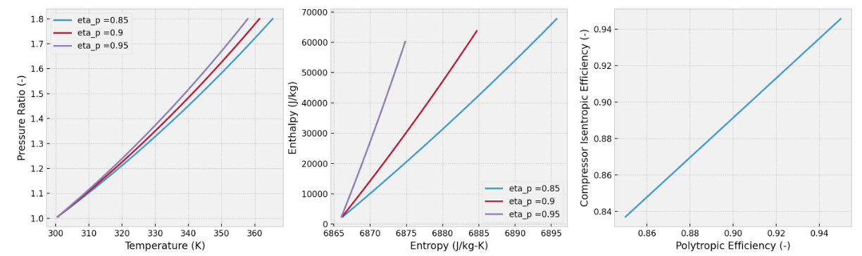
Figure: Total temperature vs pressure, $h$–$s$ diagram, and isentropic vs polytropic efficiency comparison generated using Cantera.
Why axial and mixed flow
A centrifugal compressor capable of $\pi_c \approx 1.8$ would require a large impeller diameter and diffuser, increasing the vehicle drag cross section. A single stage axial compressor can maintain a small frontal area but struggles to reach this pressure ratio without:
- excessive blade loading
- high diffusion factors
- reduced stall margin
A mixed flow topology provides a compromise:
- increased work per stage relative to axial
- reduced frontal area relative to centrifugal
- controlled diffusion through a conical meridional path
This places the design in a narrow region between traditional axial and radial machine families.
Parametric flowpath definition in CAD
The starting point is a radial cross section of the meridional flowpath defined in CAD for both topologies.
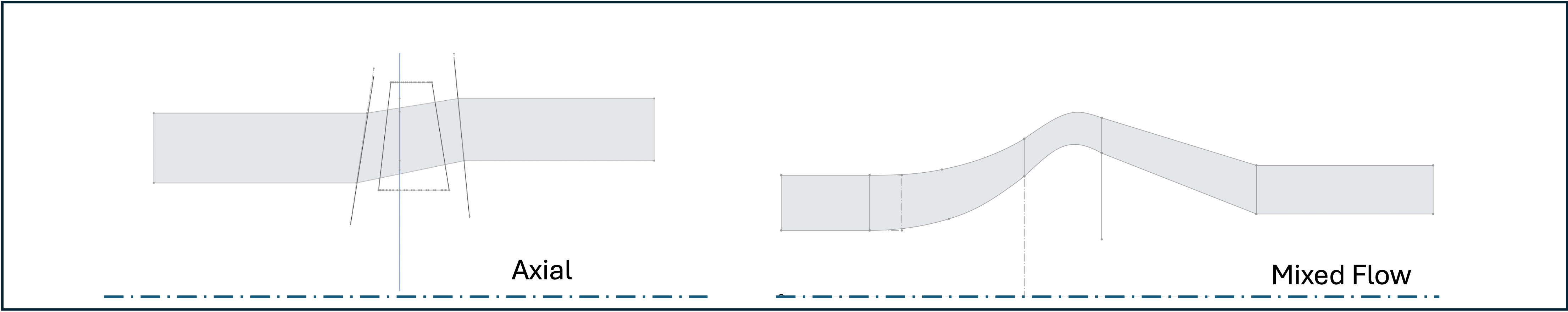
Figure: Radial cross sections used to define the hub and shroud contours for the axial and mixed flow configurations.
The full 3D fluid volume for a single periodic blade passage is then generated.
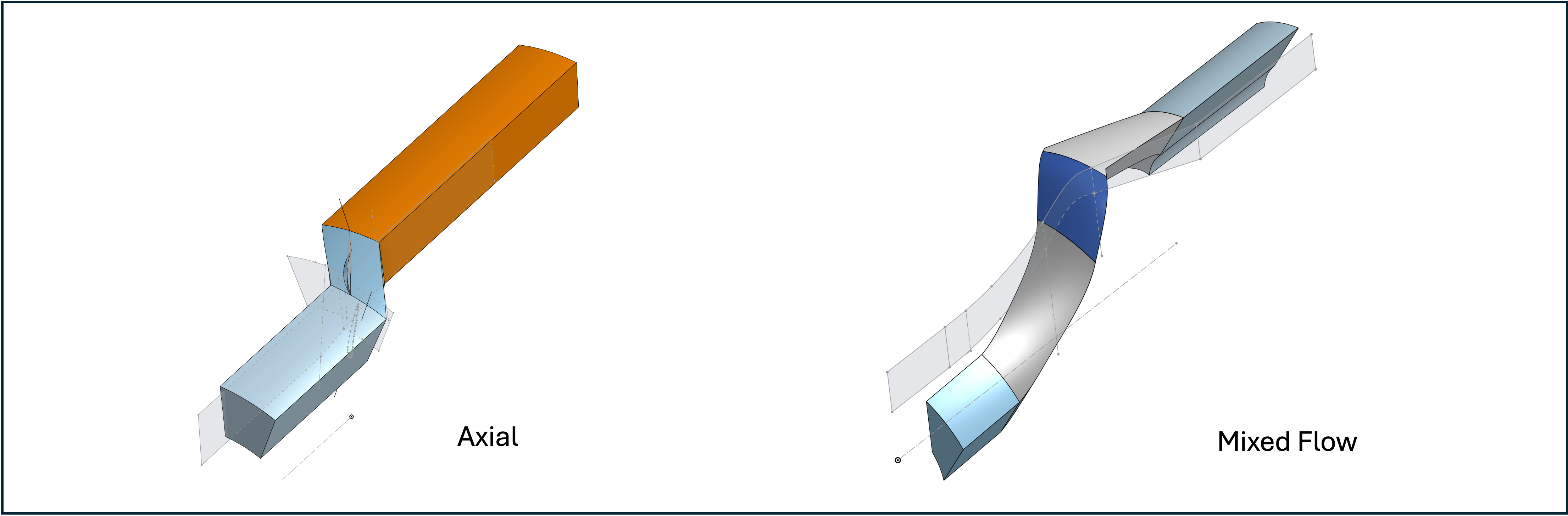
Figure: CAD definition of the periodic fluid volume. Geometry currently transitioning from Onshape to fully parametric generation in build123d.
The long term goal is a fully scriptable geometry pipeline with no manual CAD interaction.
Automatic block decomposition for structured meshing
The CAD geometry is automatically decomposed into a set of topologically consistent hexahedral blocks suitable for transfinite meshing in Gmsh. This ensures:
- perfect periodicity at passage boundaries
- controllable clustering in boundary layers
- structured indexing for turbomachinery solvers
The resulting meshes are shown below.
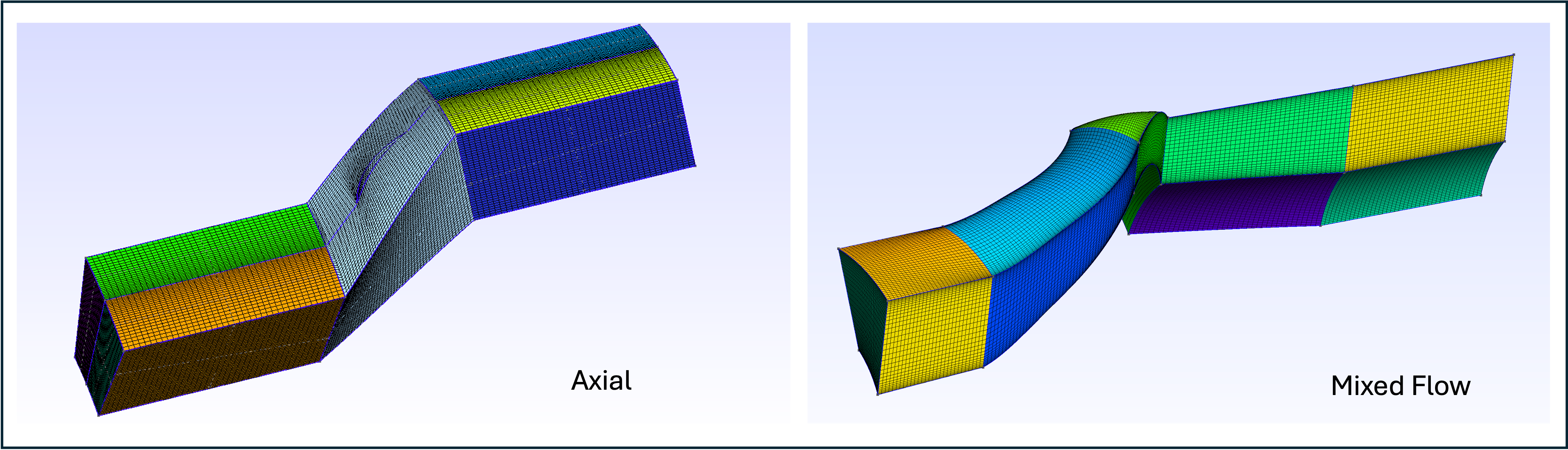
Figure: Single passage block structured meshes with periodic boundaries.
CFD solution in SU2
The meshes are solved using the turbomachinery capabilities of SU2, including:
- radial equilibrium formulation
- Giles boundary conditions at inlet and outlet
- periodic passage interfaces
Post processing is performed in ParaView to visualize pressure rise and loading distribution.
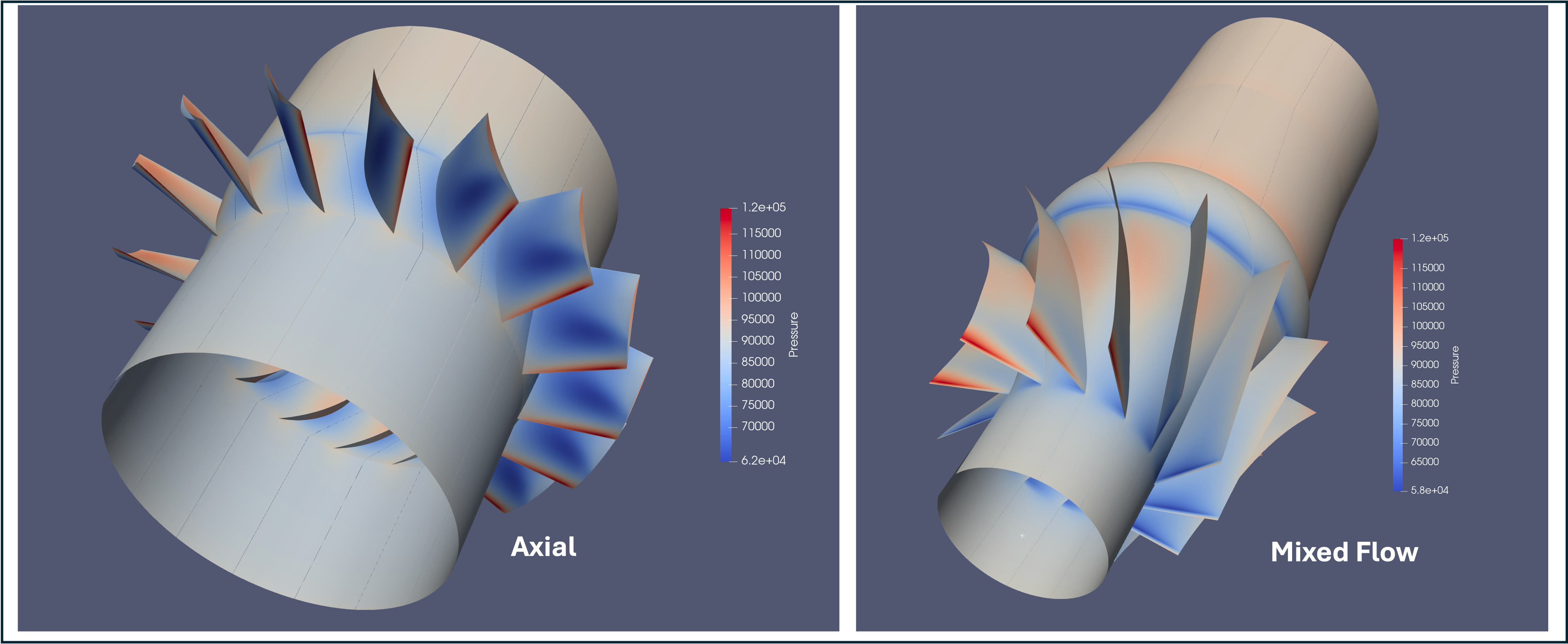
Figure: Pressure contours on blade and hub surfaces showing stage loading and diffusion.
Current results
The mixed flow configuration shows:
- higher achievable pressure ratio at comparable tip radius
- smoother diffusion through the meridional channel
- reduced peak blade loading relative to the axial case
This suggests that a mixed flow stage can deliver the required thermodynamic work while maintaining a smaller frontal area than a centrifugal alternative.
Toward a fully automated design loop
The mixed flow geometry is currently being migrated into a fully parametric build123d definition. The objective is an automated pipeline:
- Specify target $\pi_c$ and efficiency range
- Generate meridional flowpath and blade geometry
- Automatically decompose into transfinite mesh blocks
- Solve single passage CFD in SU2
- Extract pressure ratio, efficiency, and loss breakdown
This enables systematic exploration of the coupled trade space between:
- thrust capability
- vehicle drag penalty
- motor compatibility and tip speed limits
All components of the workflow are open source and scriptable, allowing large parametric studies without manual intervention.
Summary
Designing a compressor stage for compact high speed drone propulsion requires operating in a nonstandard region of the turbomachinery design space. A pressure ratio in the range $1.4$ to $2.0$ is:
- too high for a practical single stage fan
- incompatible with the drag of a centrifugal stage
A mixed flow topology combined with an automated CFD workflow provides a viable path forward. The current results indicate that this approach can deliver the required thermodynamic performance while preserving the aerodynamic constraints imposed by the vehicle.
Future work will couple the compressor map directly to propulsion system models to close the loop between aerodynamics, thermodynamics, and electrical power limits.
Ryan Blanchard PhD
Design, Research, Engineering, Data, Physics. I believe that few things in life are as rewarding as commiting yourself to a project to get something built. The feeling of seeing numerical and statistical models come to life in real-world hardware is just unbeatable.