Why Propeller Design Is Hard
A propeller is just a rotating wing, but that simple statement hides a lot of complexity.
Unlike a fixed wing, every blade section on a propeller:
- Sees a different relative velocity
- Operates at a different effective angle of attack
- Contributes simultaneously to thrust and torque
Designing a propeller therefore requires closing a loop between:
- 2D airfoil performance
- 3D blade geometry
- Integral thrust, torque, and power
This is where XFOIL and QPROP come in. XFOIL provides the sectional aerodynamics. QPROP integrates those sections into a rotating blade model and predicts the global performance.
Together, they form a fast, physics-based path from geometry → performance, which is exactly what I needed for UAV and human-powered aircraft propellers.
Theoretical Background (QPROP in a Nutshell)
QPROP is based on blade-element / momentum theory with careful accounting of velocities and induced effects. A blade element at radius $r$ sees a relative velocity composed of axial and tangential components:
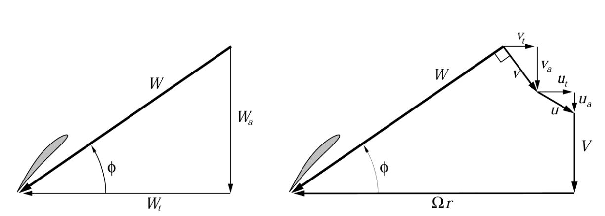 Velocity components and force decomposition used in QPROP blade-element theory
The local relative velocity magnitude is:
$$
W = \sqrt{(V_a + u_a)^2 + (\Omega r - u_t)^2}
$$
where:
- $V_a$ is axial inflow velocity
- $\Omega r$ is tangential blade speed
- $u_a, u_t$ are induced axial and tangential velocities
The blade section angle of attack depends directly on the local twist angle $\beta(r)$ and the inflow angle $\phi$:
$$
\alpha(r) = \beta(r) - \phi(r)
$$
This immediately explains why twist matters, even for propellers optimized for static thrust: each radius experiences a different inflow direction, and without twist, most of the blade would operate far from its optimal lift condition.
Thrust, Torque, and Power
For a blade element of chord $c(r)$, the differential thrust and torque are:
$$
dT = \tfrac{1}{2} \rho W^2 c \left( C_l \cos\phi - C_d \sin\phi \right) dr
$$
$$
dQ = r \, \tfrac{1}{2} \rho W^2 c \left( C_l \sin\phi + C_d \cos\phi \right) dr
$$
Integrating along the blade yields total thrust $T$ and torque $Q$, with power given by:
$$
P = Q \, \Omega
$$
Even in static thrust conditions ($V_a = 0$), the blade experiences a strong radial variation in inflow angle. A propeller optimized for static thrust still requires careful twist design to keep each section near its peak $C_l/C_d$.
Nomenclature (Following QPROP)
Using the notation from Drela’s formulation:
- $W$ — Relative velocity magnitude
- $V_a$ — Axial inflow velocity
- $\Omega r$ — Tangential blade speed
- $u_a, u_t$ — Induced velocities
- $\phi$ — Inflow angle
- $\beta$ — Blade pitch (twist) angle
- $\alpha$ — Section angle of attack
- $C_l, C_d$ — Sectional lift and drag coefficients
A full derivation is available in the original QPROP theory document:
QPROP Theory PDF
QPROP itself is written and maintained by Mark Drela, whose tools have quietly shaped decades of practical aerodynamic design:
web.mit.edu/drela/qprop
Feeding XFOIL into QPROP
QPROP does not invent airfoil aerodynamics it uses their force coefficients approximations as inputs.
For each blade section:
- XFOIL is used to generate polars $(C_l, C_d, C_m)$
- These are fitted with quadratic functions of $C_l = f(C_d)$
- QPROP uses those curve fits plus Reynolds Number and Prandtl-Glauert to predict local airfoil performance
So the workflow can capture the relevant physics:
- Airfoil choice
- Reynolds number range
- Compressibility effects at elevate local Mach Number
- Transition modeling assumptions
At the low Reynolds numbers relevant for small UAVs and human-powered aircraft, this coupling matters enormously.
Python Automation and Optimization
While QPROP is fast, running it manually is not how you design a propeller.
I built a Python wrapper around QPROP that:
- Generates candidate blade geometries (chord and twist parameterizations)
- Calls QPROP programmatically
- Parses thrust, torque, and power outputs
- Feeds results into an optimizer
This allowed me to optimize directly for objectives like:
- Maximum static thrust at fixed power
- Thrust-to-torque ratio
- Sensitivity to RPM variations
Getting this working reliably took nontrivial effort:
- Compiling legacy Fortran on macOS
- Dealing with compiler quirks and I/O formatting
- Making the wrapper robust to failed convergence cases
- Experimenting with different optimization algorithms
It was worth it. Once automated, design iteration became fast and quantitative instead of trial-and-error.
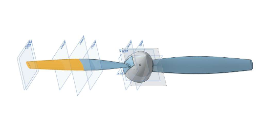
From Optimized Geometry to CAD
The final step was turning optimized blade distributions into real hardware.
The propeller was parameterized such that:
- Each blade could be split into two printable segments
- A central hub could be printed separately
- All parts could be bonded or mechanically joined
This drove constraints back into the optimization:
- Minimum chord for structural integrity
- Twist smoothness for manufacturability
- Hub-root geometry compatibility
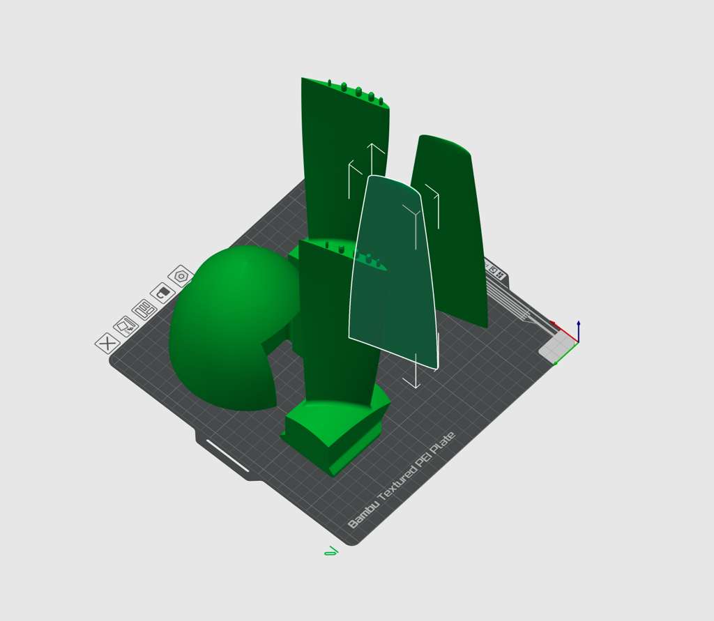
 Propeller drawn in CAD using OnShape
 To the printer!
The result was a propeller that:
- Matches the optimized aerodynamic geometry
- Can be manufactured with desktop tools
- Is suitable for static testing and iteration
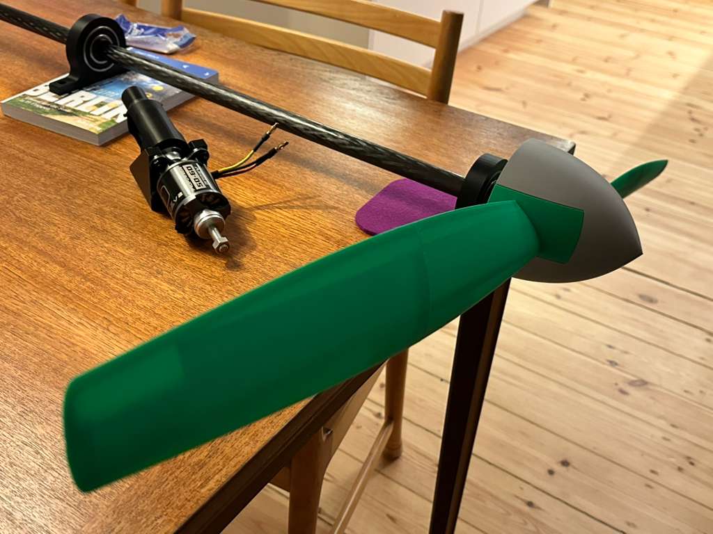 3D-printed propeller assembled from a central hub and two segments per blade.
Why This Workflow Matters
This XFOIL → QPROP → Python → CAD pipeline closes the loop from theory to hardware.
It allows:
- Fast iteration at the concept stage
- Quantitative trade studies
- Direct connection between aerodynamic assumptions and measured performance
Most importantly, it avoids over-investing in high-fidelity CFD before the fundamental design space has been explored.
For small aircraft, that leverage is everything.
Closing Thoughts
XFOIL and QPROP are not flashy tools. They are not new. But they encode decades of aerodynamic insight in a form that rewards careful thinking.
Used together (and automated properly) they form a design workflow that is fast, transparent, and grounded in physics. That combination is rare, and it’s why they remain central to how I design propellers today.
Ryan Blanchard PhD
Design, Research, Engineering, Data, Physics. I believe that few things in life are as rewarding as commiting yourself to a project to get something built. The feeling of seeing numerical and statistical models come to life in real-world hardware is just unbeatable.