Why XFOIL Matters
Designing a wing always starts with the same uncomfortable gap:
You can draw a beautiful airfoil shape but how do you know what it does aerodynamically?
For conventional aircraft, that gap is often bridged with wind-tunnel data, empirical charts, or CFD. For small UAVs and human-powered aircraft, those options are either too expensive or too slow to iterate.
XFOIL, written in Fortran at MIT by Mark Drela mit.edu/drela/xfoil, sits precisely in that gap. It provides a fast, physics-based way to go from geometry to aerodynamic coefficients lift, drag, and moment as a function of angle of attack and Reynolds number. That makes it an indispensable tool for early-stage wing design, especially when iteration speed matters.
For my pedal-powered aircraft project, XFOIL is the first link in the chain connecting a 2D airfoil sketch to a full 3D wing and, eventually, to a flyable machine. Paying the up front price for getting old Fortran to compile on Apple silicon with a series of python wrappers around it for automation has paid huge dividends for speeding up my analysis cycles.
The Low Reynolds Number Reality
One key reason XFOIL is so central to my workflow is that I operate in a very different aerodynamic regime than most airplanes.
The Reynolds number is defined as:
$$
\mathrm{Re} = \frac{\rho U c}{\mu}
$$
where:
- $ \rho $ is air density
- $ U $ is freestream velocity
- $ c $ is the characteristic length (airfoil chord)
- $ \mu $ is dynamic viscosity
Large transport aircraft operate at Reynolds numbers on the order of $10^7$–$10^8$. In contrast, small UAVs and human-powered aircraft often live in the range:
$$
\mathrm{Re} \sim 10^5 \text{ to } 10^6
$$
At these low Reynolds numbers:
- Laminar boundary layers dominate
- Separation bubbles are common
- Small geometry changes can have large aerodynamic consequences
XFOIL’s coupled inviscid panel method + boundary-layer solver is specifically designed to capture these effects efficiently.
From Geometry to Aerodynamic Coefficients
Given an airfoil shape, XFOIL solves for the pressure distribution and boundary-layer state around the perimeter, producing integrated aerodynamic coefficients:
- Lift coefficient $C_l$
- Drag coefficient $C_d$
- Moment coefficient $C_m$
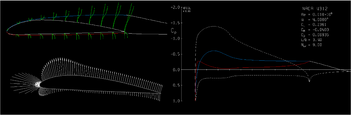 XFOIL solution showing pressure coefficient and boundary-layer state around the airfoil, along with resulting aerodynamic coefficients.
The lift coefficient is defined as:
$$
C_l = \frac{L}{\tfrac{1}{2} \rho U^2 S}
$$
This normalization allows results to be compared across scales, speeds, and densities, which are critical when extrapolating between test cases.
XFOIL allows these coefficients to be computed across:
- Angle of attack sweeps
- Reynolds number sweeps
- Different boundary-layer transition assumptions
That makes it ideal for mapping the operating envelope of an airfoil before committing to a wing design.
Circulation: The Quantity That Really Matters
While lift coefficients are convenient, the deeper physical quantity behind lift is circulation.
For a 2D airfoil, lift per unit span is related to circulation $ \Gamma $ via the Kutta–Joukowski theorem:
$$
L' = \rho U \Gamma
$$
Circulation provides a direct link between:
- Pressure distribution
- Vorticity in the flow
- Lift generation
This becomes especially important when moving from 2D airfoils to 3D wings, where the spanwise distribution of circulation determines induced drag and overall efficiency.
XFOIL provides the sectional lift data needed to build that circulation distribution across a wing.
From 2D Airfoils to a 3D Wing
A real wing is not a single airfoil, it is a spanwise distribution of airfoil sections, chord lengths, and twist angles.
For my designs, I use XFOIL to:
- Analyze candidate airfoils at local Reynolds numbers
- Select sections that perform well across the expected lift range
- Assign twist to shape the spanwise lift distribution
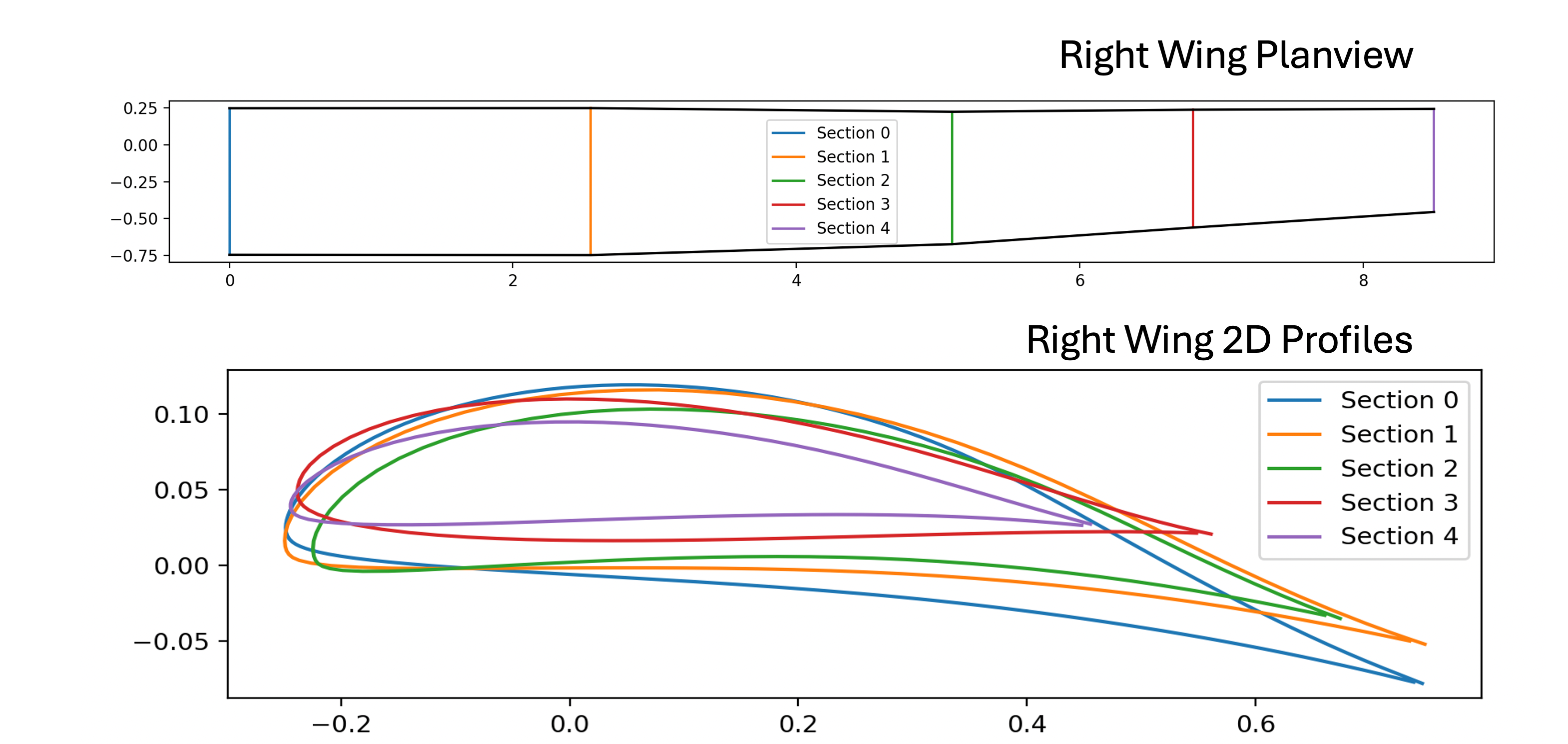 Planform layout showing spanwise airfoil sections and geometric twist distribution.
The goal is simple in principle:
- Maximize lift for a given power
- Minimize drag, especially induced drag
- Maintain gentle stall behavior
Induced Drag and Lift Distribution
For a finite wing, induced drag arises from trailing vortices and depends on how lift is distributed along the span.
In coefficient form, induced drag can be written as:
$$
C_{D_i} = \frac{C_L^2}{\pi e \, \mathrm{AR}}
$$
where:
- $ C_L $ is the wing lift coefficient
- $ \mathrm{AR} $ is aspect ratio
- $ e $ is the span efficiency factor
The efficiency factor $e$ encodes how close the actual lift distribution is to the ideal elliptical case.
$$ \Gamma(\theta)=2 b U_\infty \sum_{n=1}^{\infty} A_n \sin(n\theta), \qquad y=\frac{b}{2}\cos\theta,\ \theta\in[0,\pi] $$
then the induced drag factor comes out:
$$ e=\frac{1}{1+\sum_{n=2}^{\infty} n\left(\frac{A_n}{A_1}\right)^2} $$
$$ C_L=\pi\,AR\,A_1, \qquad C_{D_i}=\pi\,AR\sum_{n=1}^{\infty} n A_n^2 $$
By shaping the spanwise circulation (through twist, taper, and airfoil selection) induced drag can be reduced significantly. XFOIL provides the sectional data needed to make those design decisions quantitatively rather than by intuition alone.
Why This Workflow Works
XFOIL is not a replacement for CFD or experiments. Instead, it plays a very specific and valuable role:
- It is fast enough for design iteration
- It captures key low-Reynolds-number physics
- It produces interpretable aerodynamic quantities
- It enables informed 3D wing design before expensive analysis
For both my UAV work and my human-powered aircraft project, XFOIL is the tool that lets me move confidently from a sketch of an airfoil to a wing that has a realistic chance of working in the real world.
Everything downstream (lifting-line models, BEM codes, CFD, and eventually flight testing) depends on getting this first step right.
Ryan Blanchard PhD
Design, Research, Engineering, Data, Physics. I believe that few things in life are as rewarding as commiting yourself to a project to get something built. The feeling of seeing numerical and statistical models come to life in real-world hardware is just unbeatable.